(888) 702-0540 - (661) 291-1620 sales@h2wtech.com
H2W Technologies Innovation in Linear Motion
  • Home
    • LINEAR MOTORS
    • Voice Coil Actuators
    • Brushless Linear Motors
    • Brush Linear Motors
    • Single Axis Linear Stepper Motors
    • Dual Axis Linear Stepper Motors
    • Linear Induction Motors
    • Polynoids
    • ROTARY MOTORS
    • Rotary Voice Coil Actuators
    • Limited Angle Torque Motors
    • Brushless Rotary Motors
    • LINEAR STAGES
    • Voice Coil Stages
    • Linear Stepper Stages
    • Single Rail Stages
    • Dual Rail Stages
    • Crossed Roller Stages
    • Air Bearing Stages
    • Belt Stages
    • Multi-Axis Systems
    • Vacuum Compatible
    • Air Bearing Systems
    • Amplifiers & Drivers
    • System Integration
    • Linear Magnetic Brakes
    • Engineering Design Services
    • Product Selector
    • Product Sizing
    • Linear Motion Calculator
    • Rotary Motion Calculator
    • Position Control Options
    • White Papers
    • Rules of Thumb
    • Frequently Asked Questions
    • Glossary
    • Videos
  • Blog
  • About
  • Contact
  • Request a Quote
  • 0.

Multi-Axis - Linear Motor Positioning Stage

MULTI AXIS: LINEAR MOTOR DRIVEN POSITIONING STAGE

 multi-axis solution that uses direct drive linear motor technology and rotary-to-linear technology


NOTES:
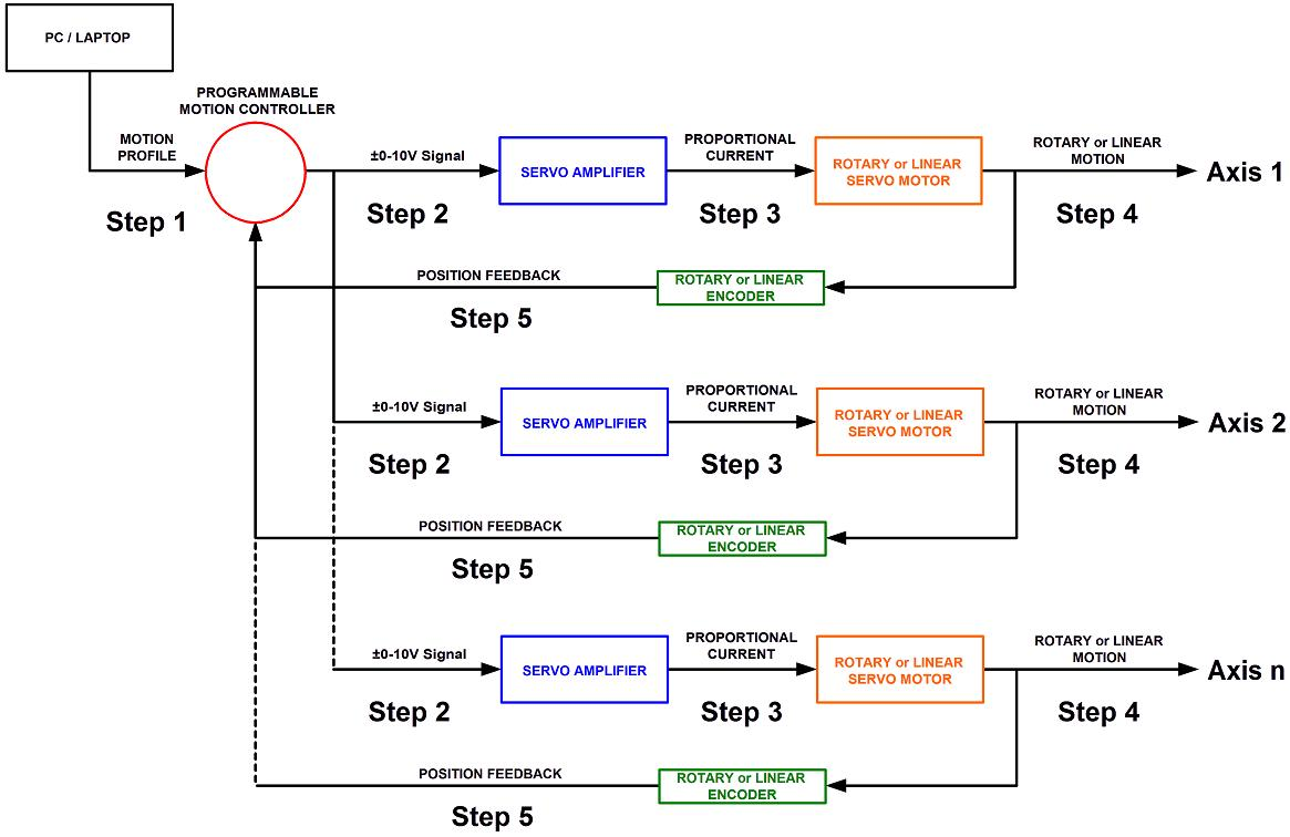
-The program or motion profile will have specific parameters for each axis of motion. Parameters such as speed, acceleration, deceleration, desired position, etc… can be different for each axis.
-The motion controller can simultaneously monitor the feedback of multiple axis for coordinated motion control.
-Depending on the particular motion controller used, the number of independent axis will vary from 2-32 axis of motion.

Step 1. A program or motion profile will be written on a PC or laptop and downloaded to the motion controller. This program will contain parameters such as speed, acceleration, deceleration, PIDs, desired position, etc…

Step 2. Based on the program parameters, the motion controller will send a +/- 10V reference signal to the servo amplifier.

Step 3. The servo amplifier will take the reference input signal and provide the necessary current to generate the required force from the motor to move to the desired position.

Step 4. The motor will move to the desired position at the programmed speed and acceleration.

Step 5: Motor position is sent back to the controller to verify that the desired position has been reached and maintained.


LINEAR MOTORS

Voice Coil Actuators Brushless Linear Motors Brush Linear Motors Single Axis Linear Stepper Motor Dual Axis Linear Stepper Motor Linear Induction Motor Polynoids

ROTARY MOTORS

Rotary Voice Coil Actuators Limited Angle Torque Motors Brushless Rotary Motors

LINEAR STAGES

Voice Coil Positioning Stages Linear Stepper Stages Single Rail Stages Dual Rail Stages Crossed Roller Stages Air Bearing Stages Belt Stages

OTHER SOLUTIONS

Multi-Axis Systems Vacuum Compatible Air Bearing Systems Amplifiers & Drivers System Integration Linear Magnetic Brakes Engineering Design Services

RESOURCES

Product Selector Product Sizing Linear Motion Calculator Rotary Motion Calculator Position Control Options White Papers Rules of Thumb Frequently Asked Questions Glossary Videos
© 2025 H2W Technologies, Inc. All rights reserved. Site Map | Terms & Conditions