A DC linear servo amplifier is required to provide power to the torquer.
Rotary voice coil actuators are supplied unhoused without bearings.
Coupling the rotary voice coil actuator to your bearing system and a rotary encoder or other feedback device yields a system that is capable of intricate angular position, velocity, and acceleration control.
Low moving inertia of the moving coil assembly allows for high angular acceleration of the payload.
Advantages:
- No Torque Ripple
- High Angular Acceleration
- No Commutation
- Zero Cogging
- Brushless
- Low Profile
Applications:
- Aerospace
- Semiconductor
- Medical
- Military
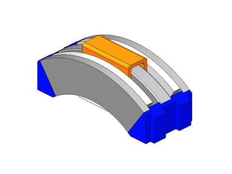
Rotary Voice Coil Motor – is an arc segmented multipole permanent magnet stator with a low inertia copper magnet wire rotor. Angular excursions are typically less than 90º. This torquer is supplied with out a shaft or bearing.
The TWR Series is comprised of a stationary, arc segmented, multipole permanent magnet stator assembly with a low inertia wound wire rotor.
Rotor: The rotor is made up of a single coil of bondable copper magnet wire. The coil is wound and preformed into the desired shape. It is held together with the bonding agents in the wire. It can be encapsulated with aluminum or plastic brackets in order to provide a means for mounting the rotor to the bearing system and payload. The maximum angular excursion is less than 90º.
Stator: The stationary stator assembly consists of multipole permanent magnets that are bonded to steel plates. The 2 opposing steel plates are spaced apart to provide a gap using end plates. The coil rotor assembly moves angularly within this gap. There is no magnetic attractive force between the stator and the rotor.
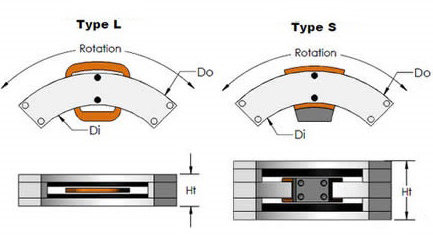
The TWR Series Torquers are available in 2 configurations.
The low profile (Type L) configuration has a smaller overall height which allows it to fit in a more compact space, but has less angular rotation for a given stator arc segment.
The second configuration (Type S) has a larger overall height but has typically twice the angular rotation per given stator arc segment when compared to the Type L torquer.
- No Torque Ripple
- High Angular Acceleration
- No Commutation
- Brushless
- Low Profile


Loading...
Because of the very low inductance of the actuator, a DC linear servo amplifier is required to provide power to the Voice Coil. A programmable motion controller is required to close the position loop on the system.
Environmental Considerations:
The NC Actuators should not be mounted in an environment that is wet or excessively dirty or in an environment with ambient temperatures (>50ºC).
Mounting
Mounting holes are provided on the housing, shaft and / or coil assemblies for mounting the actuator to customer supplied base and payload
Maintenance:
No maintenance is required.
General Description:
Bi–directional DC linear motor consisting of a moving wound coil assembly and a stationary magnet assembly.
Construction:
Plated steel magnet housing assembly, nylon or like material wound bobbin assembly. Your motor may or may not be supplied with a mounting flange or other mounting provisions refer to documentation included with shipment for custom motors.
Bearing type:
Bearings are not provided with standard models. It is the purchaser’s responsibility to supply bearings on standard models. With the magnet assembly secured, the bearing must support the coil assembly so that it is mechanically centered in the magnet assembly. Failure to center the coil assembly may lead to mechanical contact between the coil and magnet assembly. If this occurs, motor electrical shorts are possible. If your motor is supplied with bearings, refer to documentation included with shipment for additional information.
Maintenance:
Motor should be kept dry and relatively free of contamination. This motor is NOT WATER PROOF. Avoid submersion. Avoid contact with petroleum– based solvents. Alcohol can be used to remove contaminants.
Motor specifications:
Refer to catalog or outline drawing supplied with motor for mechanical dimensions and electrical specifications.
Motor Mounting:
Refer to catalog or outline drawing supplied with motor for mounting details and hole dimensions. If you motor is supplied with drilled and tapped mounting holes, refer to the recommended seating torque for screws in this document. It is recommended that a thread locking compound be used with mounting screws. Motor wires must be strain relieved.
Electrical Connections:
For voltage and current specifications, refer to product drawings or to documentation enclosed for custom motors. Your motor is supplied with 18 inch flying leads*. These wires can be cut to remove excess length if required. Connectors are available; contact a H2W representative for more information.
Motor Wire
| Function | Color |
|---|---|
| -DC | Black |
| +DC | White |
| Ground | Motor Housing |
* Some motors are supplied with custom cables; refer to documentation included with this shipment for any custom motor designs.
OPERATING A VOICE COIL MOTOR USING A FUNCTION GENERATOR
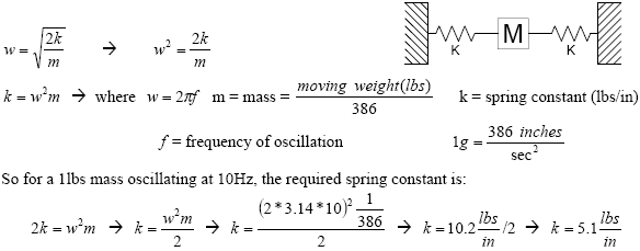
A voice coil motor can be oscillated at a set frequency in open loop operation using a function generator. See diagram 1 for operation flow.
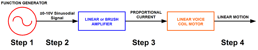
Step 1. A desired frequency and amplitude is set in the function generator.
Step 2. Based on the function generator settings, a +/- 10V reference signal is sent to the amplifier.
Step 3. The amplifier will take the reference input signal and provide the necessary current to oscillate the voice coil motor at the desired frequency. The amplitude of the frequency determines the displacement of the voice coil motor.
Step 4. The voice coil motor will oscillate at the desired frequency and displacement.
Note: 2 springs should be used with the motor to conserve energy and to provide a centering force for the moving magnet assembly of the voice coil.