The AC polynoid is an electrically operated, open loop AC linear
induction motor that provides a constant force over its entire stroke. It
can run directly off of 115 / 230 VAC line voltage or with an adjustable
frequency drive. Its direction of travel
is reversible by switching 2 of the 3 leads.
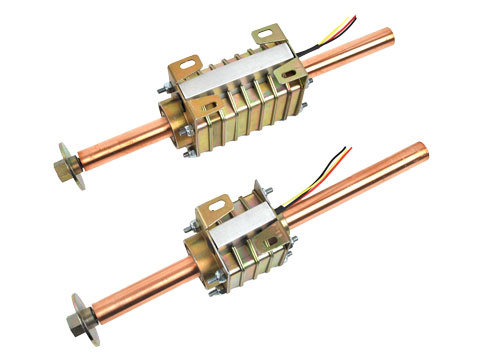
A polynoid is made up of two basic parts, a rod and a stator. The stator is a series of interconnected coils
that are housed in a toothed steel assembly that is available with fins for
improved heat dissipation. An optional holding coil is available for end
holding at one or both ends. The rod is
a custom copper clad steel shaft, with tapped mounting holes. The rod can be supplied in any length.
Polynoid linear actuators are ideal replacements for air
cylinders, and can be used to actuate electrical switch gears, for diverting
products on conveyer belts.
·
Forces to 445 N [100 Lbs]
·
Acceleration to 9.8 m/s2 [1g]
·
Speeds to 2.3 m/s [90 in/sec]
·
Optional built-in electronic brake (holding coil) for
end holding
·
Integral rulon bearings
·
Low cost, powered by AC line voltage or adjustable
speed with an inverter
·
Provides long stroke with uniform force
·
Stroke limited by end stops on moving rod
·
Limited duty cycle applications
·
V
irtually maintenance free
· Single or 3-phase AC line voltage, 50 or 60 Hz (Single-phase requires use of external capacitor)

Loading...
| Polynoid | ||||||
|---|---|---|---|---|---|---|
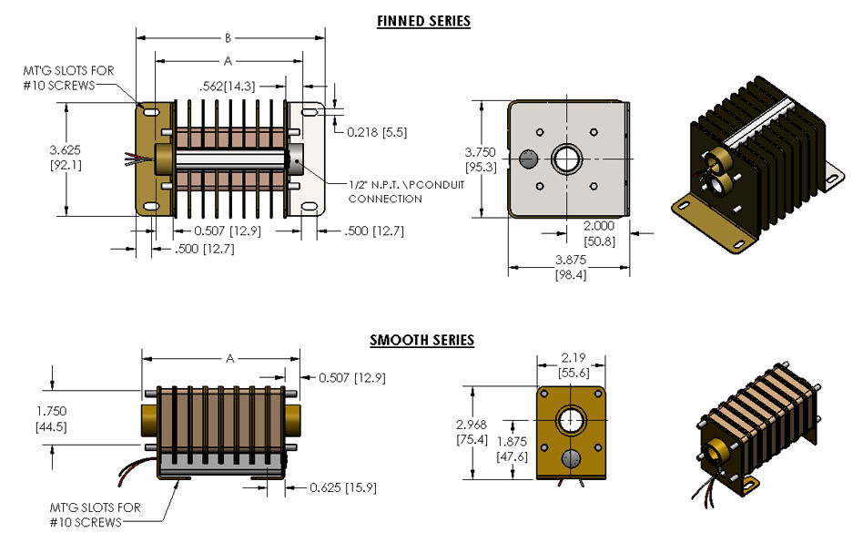
| Finned Series | Smooth Series | |||||
| Coils | A in [mm] | B in [mm] | Weight. LBS [kg] | Coils | A in [mm] | Weight. LBS [kg] |
| 2 | 2.124 ± .051 [54.2 ± 1.3] | 3.499 ± .040 [88.9 ± 1.0] | 1.7 [0.77] | 2 | 2.124 ± .051 [54.2 ± 1.3] | 0.85 [0.39] |
| 3 | 2.514 ± .056 [63.9 ± 1.4] | 3.879 ± .045 [98 .5 ± 1.1] | 1.9 [0.86] | 3 | 2.514 ± .056 [63.9 ± 1.4] | 0.86 [0.39] |
| 4 | 3.085 ± .071 [78.4 ± 1.8] | 4.450 ± .060 [113.0 ± 1.5] | 2.5 [1.1] | 4 | 3.085 ± .071 [78.4 ± 1.8] | 1.39 [0.631] |
| 6 | 4.060 ± .091 [103.1 ± 2.3] | 5.425 ± .080 [137.8 ± 2.0] | 3.2 [1.5] | 6 | 4.060 ± .091 [103.1 ± 2.3] | 1.94 [0.88] |
| 8 | 5.035 ± .111 [127.9 ± 2.8] | 6.400 ± .100 [162.6 ± 2.5] | 4.2 [1.9] | 8 | 5.035 ± .111 [127.9 ± 2.8] | 2.50 [1.14] |
| 9 | 5.045 ± .101 [128.1 ± 2.6] | 6.410 ± .090 [162.8 ± 2.3] | 4.0 [1.8] | 9 | 5.045 ± .101 [128.1 ± 2.6] | 2.20 [1.0] |
| 12 | 6.986 ± .151 [177.4 ± 3.8] | 8.351 ± .140 [211.2 ± 3.6] | 5.8 [2.6] | 12 | 6.986 ± .151 [177.4 ± 3.8] | 3.60 [1.64] |
| 24 | 13.125 ± .271 [333.4±6.8] | 14.802 ± .160 [376.0 ± 4.1] | 12.8 [5.8] | 24 |
| Polynoid Rods | ||
|---|---|---|
| Length | Catalog Number | |
| inch | mm | |
| 4 | 101.6 | LTPY001-073 |
| 6 | 152.4 | LTPY001-064 |
| 8 | 203.2 | LTPY001-066 |
| 9 | 228.6 | LTPY001-067 |
| 10 | 254.0 | LTPY001-070 |
| 12 | 304.8 | LTPY001-068 |
| 18 | 457.2 | LTPY001-074 |
| 24 | 609.2 | LTPY001-075 |
| 36 | 914.4 | LTPY001-076 |
| 48 | 1219.2 | LTPY001-077 |
| 60 | 1524.00 | LTPY001-078 |
| 72 | 1828.8 | LTPY001-079 |
| Capacitors for Single-Phase Units | ||
|---|---|---|
| Capacitor Code Number | Capacitor Rating | |
| mFd | Type | |
| C1 | 10 | 165V C |
| C2 | 43-53 | 330V E |
| C3 | 189-227 | 165V E |
| C4 | 3 | 370V C |
| C5 | 10 | 330V C |
| C6 | 88-108 | 330V E |
| C7 | 64-77 | 330V E |
| C8 | 21-25 | 330V E |
| C9 | 30-36 | 330V E |
| C10 | 4 | 370V C |
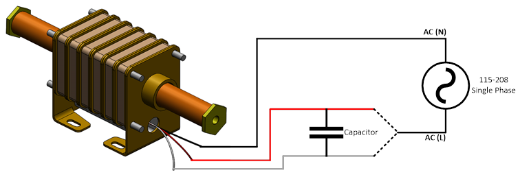
Polynoid Capacitor Connection:
The Polynoid leads should be connected to the capacitor and AC input. Refer to diagram below.
![]()
Red Wire = One side of the capacitor
White Wire = One side of the capacitor
Bridge Rectifier Diode: The polynoid holding coil leads should be connected to the bridge rectifier diode.
.png)

 Step 1. The rated single or 3-phase AC voltage is applied to the Polynoid motor.
Step 2. The Polynoid motor will start from zero speed and accelerate to the rated velocity based on frequency and mechanical load.
 Step 1. The rated single or 3-phase AC voltage is applied to the VFD.
Step 2. Based on VFD settings, a unique voltage and frequency is applied to the Polynoid motor.
Step 3. The Polynoid motor will start from zero speed and accelerate to the rated velocity based on frequency and mechanical load.