The 3-phase coil assembly can be commutated trapezoidally using integral Hall Effects or sinusodially using software commutation in conjunction with the appropriate amplifier or motion controller and encoder feedback.
The power to the motor (from a brushless servo amplifier) is supplied via a motor power cable.
Larger motors with higher forces are available, consult factory for details and drawings. Custom motors can be designed to fit customer specific application needs.
Applications:
- Coordinate measuring machines
- Pick and place machines
- Coordinate measuring machines
- Laser and water jet cutters
- Vision inspection equipment
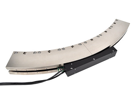
Ironless Motor
The encapsulated moving coil assembly moves through a gap in the long "U" shaped magnet assembly. A customer supplied bearing system is required to guide the moving coil assembly and to maintain a .025" [0.63 mm] clearance between the magnet and the coil assembly. There is no attractive force between the motor coil and the magnet assembly.
Advantages:
- Unlimited stroke length
- Zero cogging
- High speed and accelerations of light loads
- Low moving mass
- Multiple motors coils inside a single magnet assembly
- Uses standard 3 phase brushless amplifier
Ironless motors are available in 6 different cross sections and 5 different coil assembly lengths. Linear forces range from 1.2 lbs [5.3 N] to 173 lbs [771 N] continuous (100% duty cycle), 3.6 lbs [16.0 N] to 517 lbs [2300 N] peak (10% duty cycle).
Ironless motors consist of a stationary magnet track and a moving coil assembly.
Stationary Magnet Assembly: The "U" shaped magnet assembly is made up of nickel-plated steel back iron and Neodymium permanent magnets. The magnets are bonded to the 2 parallel steel plates and the plates are bolted to a steel spacer bar. Threaded and thru holes are available in the steel back iron for mounting the magnet assembly to the customer supplied base plate. The magnet assembly is available in cross sectional widths from 0.82" to 1.73 " [20.8 mm to 44 mm]. The length of the magnet assembly is a function of the arc.
Moving Coil Assembly: The coil assembly is comprised of a 3 phase copper motor winding, an aluminum mounting bracket and an optional Hall Effect board that are all vacuum encapsulated with epoxy. Mounting holes in the aluminum bracket are provided for attaching the secondary to the moving member of the customer supplied table assembly. The coil assembly is available in many different widths and lengths, to meet the customers force and packaging requirements. Multiple coils can be supplied with a single magnet assembly to allow for independent moving heads or they can be coupled together to produce larger forces.

Loading...
Required Electronics:
The motor requires either a trapezoidal or sinusoidal 3 phase brushless amplifier with power supply that is rated with sufficient current and voltage to meet the motion requirements. The inductance of the linear motor coil should be greater than the minimum load inductance of the servo amplifier.
Environmental Considerations:
The brushless motor is an open type motor and should not be mounted in an environment that is wet or excessively dirty. It should be protected with some type of bellows or cover when installed by the customer.
Mounting:
The brushless linear motor should be mounted to flat (better than .003"/ ft [246 microns / m] and stiff surface. Threaded and thru holes in the magnet assembly and threaded holes in the coil assembly are present for the mounting of the motor to the customers system. A cable carrier must be provided by the customer to route the motor and Hall Effect cable. The motor may be mounted in any orientation.
Maintenance:
The ball bearing guides in the stage should be periodically lubricated with the manufacturers recommended grease. The open glass encoder scale should be wiped with a glass cleaner occasionally to ensure trouble free operation.