H2W Technologies linear stepper motors are ideal for open loop positioning applications with light payloads. They can be used at speeds up to 80 in /sec [2 m/sec] and strokes up to 144” [3.6 m]. Linear stepper motors are capable of very precise position, velocity and acceleration control when coupled with a microstepping drive and indexer.
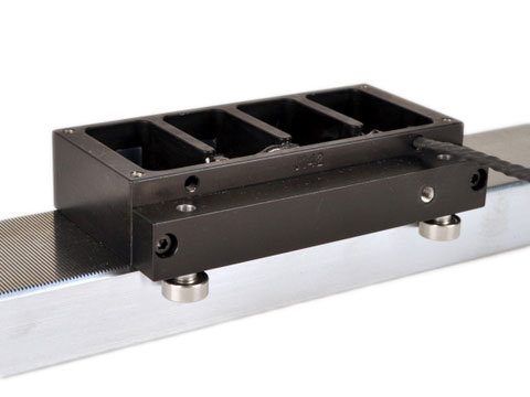
The short moving assembly called a “forcer” is guided by either roller or air-bearings along he precision ground track called a “platen”. The bearings are designed to support the customer’s payload and to maintain the required .001” [0.025 mm] gap between the platen and the forcer.
The step and direction signal from a microstepping drive, to the 2 or 4 phase forcer is supplied via a power cable. The motion achieved with a full step is .010” [250 microns] and with a microstep it’s .00004” [1 micron].
The linear stepper motor is a complete positioning stage with the motor, the bearings and the positioning system all built into one compact package.
Integrating a linear encoder with the stepper provides a closed loop system.
The Linear Stepper Motor consists of 2 main parts:

The short moving assembly called a “forcer” is guided by either roller or air-bearings along he precision ground track called a “platen”. The bearings are designed to support the customer’s payload and to maintain the required .001” [0.025 mm] gap between the platen and the forcer.
The step and direction signal from a microstepping drive, to the 2 or 4 phase forcer is supplied via a power cable. The motion achieved with a full step is .010” [250 microns] and with a microstep it’s .00004” [1 micron].
The linear stepper motor is a complete positioning stage with the motor, the bearings and the positioning system all built into one compact package.
Integrating a linear encoder with the stepper provides a closed loop system.
Advantages:
- Low profile and small cross section
- High Speed
- Low cost positioning stage solution
- No servo tuning required
- Multiple forcers on a single platen
Applications:
- Pick and Place
- Wire bonders
- Parts transfer
- Fiber optic
The Linear Stepper Motor consists of 2 main parts:
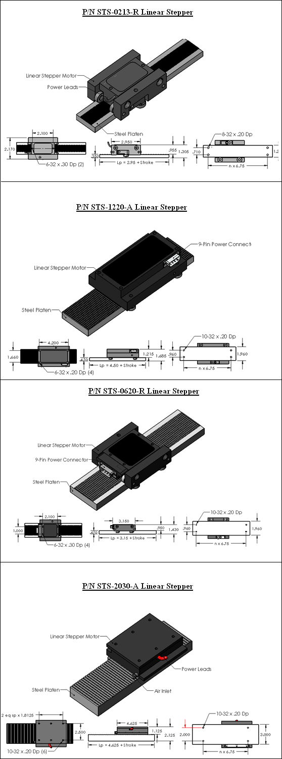
- Moving Forcer Assembly: The forcer is made up of an aluminum housing that contains the motor windings, lamination stacks, and permanent magnets. The active surface of the lamination is slotted to form teeth with a pitch of .040" [1 mm]. The ends of the coil are brought out to either a "D" connector or to flying leads. Mounting holes on the top surface of the forcer are for attaching the customer's payload. The forcer comes in different widths and lengths, depending on the required force. Multiple forcers can be supplied with a single platen to allow for independent moving heads.
- Long Stationary Platen:The platen is a precision ground steel bar or tube that is slotted to form .020" [0.50 mm] wide teeth on the surface. The bar is hard chrome plated and filled with epoxy to provide a flat air-bearing surface for the platen. The platen is available in widths from 1.25" to 3.0 " [31.8 mm to 76.2 mm]. The length of the platen is a function of the stroke. Single piece platens are available as long as 144 inches [3.6 m]. For longer strokes the platens will be supplied in sections.

Loading...
Required Electronics:
The linear stepper motor requires a full step or microstepping driver with power supply that is rated with sufficient current and voltage to meet the motion requirements. With full stepping, the forcer will move .010" [.25 mm] for each step. With microstepping the forcer will divide the fullstep by the number of microsteps. With 256 microsteps / full step, the microstep will be .010" [.25 mm] / 256 = 0.00004" [1 micron]
Environmental Considerations:
The linear stepper motor is a precision device and should not be mounted in an environment that is wet or excessively dirty. Debris should not be allowed to accumulate on the platen.
Mounting:
The platen should be mounted to a flat (better than .003"/ ft [246 microns / m]) and stiff surface. Threaded holes on the bottom of the platen are present for mounting to the customers system. The forcer has threaded holes on the top surface for attaching the payload. The linear stepper motor may be mounted in any orientation. When mounting the platen with the forcer moving vertical, it should be noted that the forcer will be required to generate additional force due to gravity and that the ball bearing forcer will slide down to the bottom when power fails. Turning off the air to an air bearing forcer will lock the forcer in place.
Setting The Air Gap On Single Axis Linear Stepper with Roller Bearing:The forcer air gap should be set to .0015-.002 inches [38 – 50 microns]. If the air gap is properly set, the stepper motor should be able to move freely along the entire length of the platen. If the forcer becomes difficult to move manually or it physically makes contact with the platen, the air gap will need to be reset. Instructions on how to properly set the motor airgap can be downloaded below:

LMSS Series Linear Stepper
Roller Bearing Motor
Installation
Prior to placing the Forcer on the Platen both surfaces must be cleaned. Use this method:
1. Apply masking tape to lamination surface of the Forcer to remove any metallic contaminants.
2. Using alcohol, clean both surfaces to remove any adhesive residue and any other contaminants on the Forcer and the Platen.
Note: Apply small amount of alcohol to cloth for cleaning. Never pour or drip alcohol or other chemicals onto the forcer or platen surfaces.
3. Wax and polish Platen and Forcer surfaces. ( Turtle Wax ). Remove any visible residue.
Adjust Air Gap
Factory preset to 0.0015”.
Note: When receiving the Forcer and the Platen, the air gap is already set to 0.0015”. (Increasing the air gap will decrease the force). Use the following instructions only if you need to reset the air gap.
1. Carefully remove the Forcer from the platen by sliding off the Forcer of the end of the Platen. (So as not to score the Forcer and the Platen surfaces).
2. Loosen the four screws (1 turn) on the bearing kits using an Allen key.
3. Center the shim on the toothed section of the Platen.
4. Place the Forcer on the Platen. Be sure that the shim is only between the Forcer and the Platen, and not between the wheels and the Platen.
5. Apply downward pressure on both bearing kits only (the Forcer is attached magnetically) and then tighten the four screws to 30 in–lbs of torque.
6. Slide the Forcer down the Platen while holding the shim in place and remove the shim.
Maintenance:
Waxing of the Forcer lamination for corrosion protection is recommended every month (or as needed) depending on environmental conditions (i.e. humidity and moisture).
Operation Considerations:
The motor must always be operated within the specified operating parameter limits. Exceeding those limits will permanently damage the motor. The forcer must never touch the platen during operation. Equal horizontal and vertical air gap must be maintained. The following steps must be completed to ensure safe and proper operation.
1. Verify that all electrical wiring and cables are properly connected. Refer to the manual provided with the control for this information.
2. Adjust the stepper driver current to match the motor’s current specification.
3. Strain relieve the wires prior to operating.
AY0165A00 Leadwire Connection (9 pin to flying leads)

When a Male D Sub connector is used, use the pin numbers to connect the forcer.
When flying leads are used, use the color codes to connect the forcer.
Air Bearing Motor
Cleaning the Forcer and Platen
Prior to placing the Forcer on the Platen both surfaces must be cleaned.
Use this method:
1. Apply masking tape to lamination surface of the Forcer. Removing the tape removes large particle contaminants.
2. Using alcohol, clean both surfaces to remove any adhesive residue and any other contaminants on the Forcer and the Platen.
Note: Apply small amount of alcohol to cloth for cleaning. Never pour or drip alcohol or other chemicals onto the forcer or platen surfaces.
3. Wax and polish Platen and Forcer surfaces. ( Turtle Wax ). Remove any visible residue.
Cleaning the Air Bearings
Required if the forcer is not lifting between 0.0005” – 0.001” ( i.e. rubbing on the Platen).
1. Using a small screw driver, unscrew one air bearing.
2. Blow compressed air through the bearing in both directions.
3. Screw the air bearing back to its original position.
Note: Do not mix the air bearings, they have to be installed at their original position.
Installation: Mounting the Forcer on the Platen
1. Before placing the forcer on the platen be sure there is at least 60 psi of regulated and filtered air flowing through the forcer.
2. At one end of the platen, carefully slide the Forcer onto the Platen. (BE EXTREMELY CAREFUL).
Removing the Forcer from the Platen
1. Before moving the forcer, be sure there is at least 60 psi of regulated and filtered air flowing through the forcer.
2. Carefully slide the Forcer to one end of the Platen and remove it. (BE EXTREMELY CAREFUL).
Maintenance
Waxing of the Forcer lamination for corrosion protection is recommended every month (or sooner) depending on environmental conditions (i.e. humidity and moisture).
Operation Considerations
The motor must always be operated within the specified operating parameter limits. Exceeding those limits will permanently damage the motor. The forcer must never touch the platen during operation. Equal horizontal and vertical air gap must be maintained. The following steps must be completed to ensure safe and proper operation.
1. Verify that all electrical wiring and cables are properly connected. Refer to the manual provided with the control for this information.
2. Adjust the stepper driver current to match the motor’s current specification.
3. Strain relieve the wires prior to operating.
The linear stepper motor requires a full step or microstepping driver with power supply that is rated with sufficient current and voltage to meet the motion requirements. With full stepping, the forcer will move .010" [.25 mm] for each step. With microstepping the forcer will divide the fullstep by the number of microsteps. With 256 microsteps / full step, the microstep will be .010" [.25 mm] / 256 = 0.00004" [1 micron]
Environmental Considerations:
The linear stepper motor is a precision device and should not be mounted in an environment that is wet or excessively dirty. Debris should not be allowed to accumulate on the platen.
Mounting:
The platen should be mounted to a flat (better than .003"/ ft [246 microns / m]) and stiff surface. Threaded holes on the bottom of the platen are present for mounting to the customers system. The forcer has threaded holes on the top surface for attaching the payload. The linear stepper motor may be mounted in any orientation. When mounting the platen with the forcer moving vertical, it should be noted that the forcer will be required to generate additional force due to gravity and that the ball bearing forcer will slide down to the bottom when power fails. Turning off the air to an air bearing forcer will lock the forcer in place.
Setting The Air Gap On Single Axis Linear Stepper with Roller Bearing:The forcer air gap should be set to .0015-.002 inches [38 – 50 microns]. If the air gap is properly set, the stepper motor should be able to move freely along the entire length of the platen. If the forcer becomes difficult to move manually or it physically makes contact with the platen, the air gap will need to be reset. Instructions on how to properly set the motor airgap can be downloaded below:
LMSS Series Linear Stepper
Roller Bearing Motor
Installation
Prior to placing the Forcer on the Platen both surfaces must be cleaned. Use this method:
1. Apply masking tape to lamination surface of the Forcer to remove any metallic contaminants.
2. Using alcohol, clean both surfaces to remove any adhesive residue and any other contaminants on the Forcer and the Platen.
Note: Apply small amount of alcohol to cloth for cleaning. Never pour or drip alcohol or other chemicals onto the forcer or platen surfaces.
3. Wax and polish Platen and Forcer surfaces. ( Turtle Wax ). Remove any visible residue.
Adjust Air Gap
Factory preset to 0.0015”.
Note: When receiving the Forcer and the Platen, the air gap is already set to 0.0015”. (Increasing the air gap will decrease the force). Use the following instructions only if you need to reset the air gap.
1. Carefully remove the Forcer from the platen by sliding off the Forcer of the end of the Platen. (So as not to score the Forcer and the Platen surfaces).
2. Loosen the four screws (1 turn) on the bearing kits using an Allen key.
3. Center the shim on the toothed section of the Platen.
4. Place the Forcer on the Platen. Be sure that the shim is only between the Forcer and the Platen, and not between the wheels and the Platen.
5. Apply downward pressure on both bearing kits only (the Forcer is attached magnetically) and then tighten the four screws to 30 in–lbs of torque.
6. Slide the Forcer down the Platen while holding the shim in place and remove the shim.
Maintenance:
Waxing of the Forcer lamination for corrosion protection is recommended every month (or as needed) depending on environmental conditions (i.e. humidity and moisture).
Operation Considerations:
The motor must always be operated within the specified operating parameter limits. Exceeding those limits will permanently damage the motor. The forcer must never touch the platen during operation. Equal horizontal and vertical air gap must be maintained. The following steps must be completed to ensure safe and proper operation.
1. Verify that all electrical wiring and cables are properly connected. Refer to the manual provided with the control for this information.
2. Adjust the stepper driver current to match the motor’s current specification.
3. Strain relieve the wires prior to operating.
AY0165A00 Leadwire Connection (9 pin to flying leads)
| Color | Pin# | Description |
|---|---|---|
| White | 1 | A1+ Winding |
| 2 | N.C. | |
| Green | 3 | B1+ Winding |
| 4 | N.C. | |
| Black | 5 | Ground |
| 6 | N.C. | |
| Red | 7 | A1- Winding |
| 8 | N.C. | |
| Orange | 9 | B1- Winding |
6
7
8
9
1
2
3
4
5
Male (D Sub)
When a Male D Sub connector is used, use the pin numbers to connect the forcer.
When flying leads are used, use the color codes to connect the forcer.
Air Bearing Motor
Cleaning the Forcer and Platen
Prior to placing the Forcer on the Platen both surfaces must be cleaned.
Use this method:
1. Apply masking tape to lamination surface of the Forcer. Removing the tape removes large particle contaminants.
2. Using alcohol, clean both surfaces to remove any adhesive residue and any other contaminants on the Forcer and the Platen.
Note: Apply small amount of alcohol to cloth for cleaning. Never pour or drip alcohol or other chemicals onto the forcer or platen surfaces.
3. Wax and polish Platen and Forcer surfaces. ( Turtle Wax ). Remove any visible residue.
Cleaning the Air Bearings
Required if the forcer is not lifting between 0.0005” – 0.001” ( i.e. rubbing on the Platen).
1. Using a small screw driver, unscrew one air bearing.
2. Blow compressed air through the bearing in both directions.
3. Screw the air bearing back to its original position.
Note: Do not mix the air bearings, they have to be installed at their original position.
Installation: Mounting the Forcer on the Platen
1. Before placing the forcer on the platen be sure there is at least 60 psi of regulated and filtered air flowing through the forcer.
2. At one end of the platen, carefully slide the Forcer onto the Platen. (BE EXTREMELY CAREFUL).
Removing the Forcer from the Platen
1. Before moving the forcer, be sure there is at least 60 psi of regulated and filtered air flowing through the forcer.
2. Carefully slide the Forcer to one end of the Platen and remove it. (BE EXTREMELY CAREFUL).
Maintenance
Waxing of the Forcer lamination for corrosion protection is recommended every month (or sooner) depending on environmental conditions (i.e. humidity and moisture).
Operation Considerations
The motor must always be operated within the specified operating parameter limits. Exceeding those limits will permanently damage the motor. The forcer must never touch the platen during operation. Equal horizontal and vertical air gap must be maintained. The following steps must be completed to ensure safe and proper operation.
1. Verify that all electrical wiring and cables are properly connected. Refer to the manual provided with the control for this information.
2. Adjust the stepper driver current to match the motor’s current specification.
3. Strain relieve the wires prior to operating.
Coming Soon
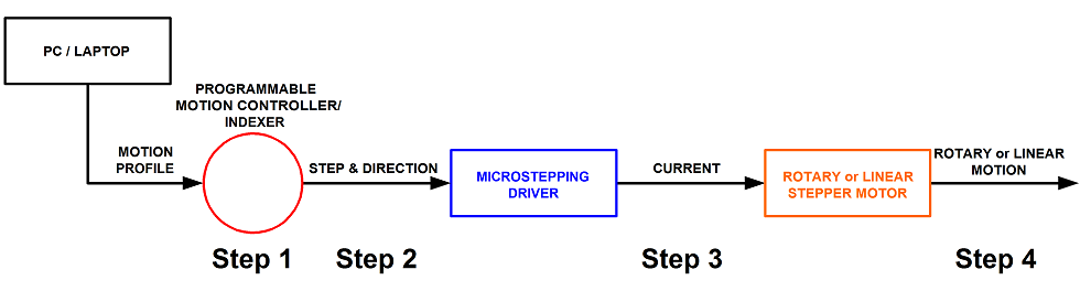
In order for the linear stepper motor to operate properly, it will need to be connected
to a motion controller or indexer and a stepper motor driver (with power supply).
See diagram 1 for operation flow.
Step 1. A program or motion profile will be written on a PC or laptop and downloaded to the motion controller/indexer. This program will contain parameters such as speed, acceleration, deceleration, desired move, etc…
Step 2. Based on the program parameters, the motion controller/indexer will command the needed number of steps in the desired direction in order to move the desired amount.
Step 3. The microstepping driver will take the step & direction input signals and move the motor using the drivers set current. The bus voltage of the microstepping driver determines the max motor speed.
Step 4. The motor will move the desired amount at the programmed speed and acceleration.