Dual-axis planar linear stepper motors are ideal for open loop positioning applications with light payloads. They can be used at speeds up to 80 in /sec [2m/sec] and strokes up to 40” x 60” [1 m x 1.5 m]. Linear stepper motors are capable of very precise position, velocity and acceleration control when coupled with a microstepping drive and indexer.
The moving assembly called the “forcer” is supported by magnetically preloaded air-bearings imbedded in the active surface of the forcer between the forcer and platen. The bearings are designed to support the customer’s payload and to maintain the required .001” [0.025 mm] gap between the platen and the forcer.
The two axis step and direction signal from a microstepping drive, to the 2 or 4 phase forcer is supplied via a power cable. The motion achieved with a full step is .010” [250 microns] and with a microstep it’s .00004” [1 micron].
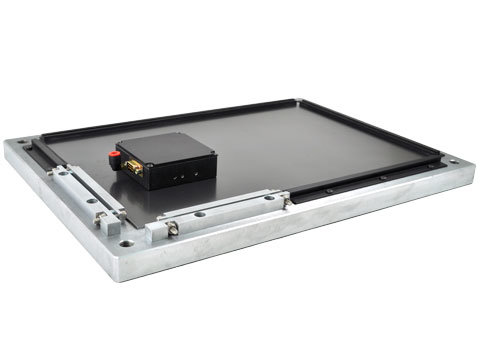
The dual-axis planar linear stepper motor is a complete positioning stage with the motor, the bearings and the positioning system all built into one compact package.
Integrating a linear encoder with the stepper motor provides a closed loop system.
The dual-axis planar linear stepper motor consists of two main parts:
1.svg)
11.svg)
The moving assembly called the “forcer” is supported by magnetically preloaded air-bearings imbedded in the active surface of the forcer between the forcer and platen. The bearings are designed to support the customer’s payload and to maintain the required .001” [0.025 mm] gap between the platen and the forcer.
The two axis step and direction signal from a microstepping drive, to the 2 or 4 phase forcer is supplied via a power cable. The motion achieved with a full step is .010” [250 microns] and with a microstep it’s .00004” [1 micron].
The dual-axis planar linear stepper motor is a complete positioning stage with the motor, the bearings and the positioning system all built into one compact package.
Integrating a linear encoder with the stepper motor provides a closed loop system.
Advantages:
- Low profile and small cross section
- High Speed
- Low cost positioning stage solution
- No servo tuning required
- Multiple forcers on a single platen
Applications:
- Pick and Place
- Wire bonders
- Parts transfer
- Fiber optic
The dual-axis planar linear stepper motor consists of two main parts:
- Moving Forcer Assembly: The forcer is made up of an aluminium housing that contains the motor windings, lamination stacks, and permanent magnets. The active surface of the lamination is slotted to form teeth with a pitch of .040" [1 mm]. The ends of the coil are brought out to either a "D" connector or to flying leads. Mounting holes on the top surface of the forcer are for attaching the customer's payload. The forcer comes in different widths and lengths, depending on the required force. Multiple forcers can be supplied with a single platen to allow for independent moving heads.
- Platen: The platen is a precision ground steel plate that is slotted to form 0.02” x 0.02” [0.50x 0.50 mm] square teeth on the surface. The spaces between the platen teeth are filled with epoxy to provide a flat air-bearing surface for the forcer. The stroke of the forcer is a function of the length and width of the platen. Platens can be manufactured in different shapes with a multitude of mounting configurations.

Loading...
More Information Coming Soon
Required Electronics:
The linear stepper motor requires a full step or microstepping driver with power supply that is rated with sufficient current and voltage to meet the motion requirements. With full stepping, the forcer will move .010" [.25 mm] for each step. With microstepping the forcer will divide the fullstep by the number of microsteps. With 256 microsteps / full step, the microstep will be .010" [.25 mm] / 256 = 0.00004" [1 micron]
Environmental Considerations:
The linear stepper motor is a precision device and should not be mounted in an environment that is wet or excessively dirty. Debris should not be allowed to accumulate on the platen.
Mounting:
The platen should be mounted to a flat (better than .003"/ ft [246 microns / m]) and stiff surface. Threaded holes on the bottom of the platen are present for mounting to the customers system. The forcer has threaded holes on the top surface for attaching the payload. The linear stepper motor may be mounted in any orientation. When mounting the platen with the forcer moving vertical, it should be noted that the forcer will be required to generate additional force due to gravity and that the ball bearing forcer will slide down to the bottom when power fails. Turning off the air to an air bearing forcer will lock the forcer in place.
LMDS Series Dual Axis Linear Stepper Motor
Items Required but NOT Included
1. A regulated 80 PSI air supply with a 5 micron filter for each motor. A water separator is also required.
2. Two or four phase, 2 ampere (micro) stepper motor driver/controller for each motor.
Cleaning the Forcer and Platen
Prior to placing the Forcer on the Platen both surfaces must be cleaned. Use this method:
1. Apply masking tape to lamination surface of the Forcer. Removing the tape removes large particle contaminants.
2. Using alcohol, clean both surfaces to remove any adhesive residue and any other contaminants on the Forcer and the Platen.
Note: Apply small amount of alcohol to cloth for cleaning. Never pour or drip alcohol or other chemicals onto the forcer or platen surfaces.
3. Wax and polish Platen and Forcer surfaces. ( i.e. Turtle Wax ). Remove any visible residue.
Cleaning the Air Bearings
Required if the forcer is not lifting between 0.0005” – 0.001” ( i.e. rubbing on the Platen ).
1. Using a small screw driver, unscrew one air bearing.
2. Blow compressed air through the bearing in both directions.
3. Screw the air bearing back to its original position.
Note: Do not mix the air bearings, they have to be installed at their original position.
Installation:
Mounting the Forcer on the Platen
1. Before placing the forcer on the platen be sure there is at least 60 psi of regulated and filtered air flowing through the forcer.
2. Use the lifting tool (in reverse) to gently, place the forcer on the platen. Be careful not to place your fingers between forcer and platen.
Removing the Forcer from the Platen
1. Before moving the forcer, be sure there is at least 60 psi of regulated air supply with a 5 µm air filter flowing through the forcer.
2. Place lifting tool (provided) in slot on the side of the forcer. Gently, pry the forcer from the platen with the tool. Lift the forcer and remove it from the platen. Be careful not to place your fingers between forcer and platen.
Maintenance
Waxing of the Forcer lamination for corrosion protection is recommended every month (or as needed) depending on environmental conditions (i.e. humidity and moisture).
Operation Considerations
The motor must always be operated within the specified operating parameter limits. Exceeding those limits will permanently damage the motor. The following steps must be completed to ensure safe and proper operation.
1. Verify that all electrical wiring and cables are properly connected. Refer to the manual provided with the control for this information.
2. Adjust the stepper driver current to match the motor’s current specification.
3. Strain relieve the wires prior to operating.

MULTI AXIS: LINEAR STEPPER MOTOR

NOTES:
-The program or motion profile will have specific parameters for each axis of motion. Parameters such as speed, acceleration, deceleration, desired move, etc… can be different for each axis.
-Depending on the particular motion controller/indexer used, the number of independent axis will vary from 2-32 axis of motion.
Step 1. A program or motion profile will be written on a PC or laptop and downloaded to the motion controller/indexer. This program will contain parameters such as speed, acceleration, deceleration, desired move, etc…
Step 2. Based on the program parameters, the motion controller/indexer will command the needed number of steps in the desired direction in order to move the motor the desired distance.
Step 3. The microstepping driver will take the step & direction input signals and move the motor using the drivers set current. The bus voltage of the microstepping driver determines the max motor speed.
Step 4. The motor will move the desired amount at the programmed speed and acceleration.