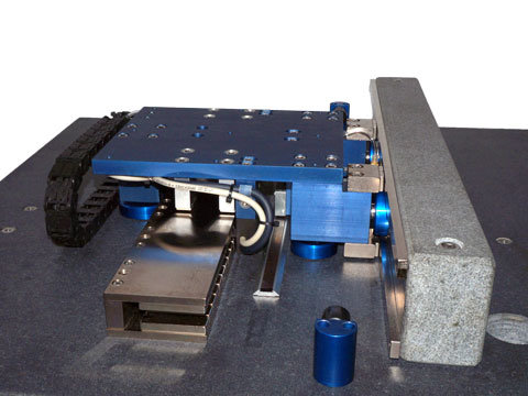
The ironless core coil assembly is used as the drive mechanism for the AB stage because of its smooth, non-cogging operation. The lightweight of the coil and table assembly allows for high acceleration of light loads.
The air bearings, which are used for supporting and guiding the payload, float on a cushion of air. This ensures that there are no wearing components in the system. The air bearings are not limited to acceleration limits like their mechanical counterparts where balls and rollers can slide instead of roll at high accelerations.
The stiff cross section of the granite base of the stage ensures a flat straight stable platform for the payload to ride on and does not require any special mounting considerations.
Bellows (folded way covers) with a 12:1 extension to compression ratio may be added to an ABS stage.
The power for the moving 3 phase coil assembly, encoder and limit switches is routed through shielded flat ribbon cable. Special consideration was made to separate the power and signal cables from each other to reduce the effects of noise on the system. The power cable for the coil assembly and a vacant cable for the customers payload power usage are installed on one side of the stage and the encoder signal, limit switch and an additional vacant signal cable for the customers payload signal usage is provided on the other side of the stage. Standard connectors are provided.
The ABS positioning stage incorporates the latest in linear motion technology:
- Motors: Non-contact 3 Phase Brushless Linear Motor, Ironless Core, commutated either sinusoidally or trapezoidally with Hall Effects. The encapsulated coil assembly moves and the multi pole permanent magnet assembly is stationary. The lightweight coil assembly allows for higher acceleration of light payloads.
- Bearings: Linear guidance is achieved by using magnetically preloaded, porous carbon or ceramic air bearings; 3 on the top surface and 2 on the side surface. The bearings are mounted on spherical surfaces. Clean, dry filtered air must be supplied to the moving table of the ABS stage.
- Encoders: Non-contact glass or metal scale optical linear encoders with a reference mark for homing. Multiple reference marks are available and are spaced every 50 mm down the length of the scale. Typical encoder output is A and B square wave signals but sinusoidal output is available as an option
- Limit Switches: End of travel limit switches are included at both ends of the stroke. The switches can be either active high (5V to 24V) or active low. The switches can be used to shut down the amplifier or to signal the controller that an error has occurred. The limit switches are typically an integral part of the encoder, but can be mounted separately if required.
- Cable Carriers: Cable guidance is achieved by using flat, shielded ribbon cable. Two additional unused shielded flat ribbon cables are supplied for customer usage with the stage. The 2 power cables for the stage and customer payload are installed on one side of the stage and the 2 signal cables for encoder, limit switch and customer payload are installed separately on the of the stage.
- Bellows: The ABS comes standard with neoprene / nylon bellows with Mylar stiffeners.
- Hard Stops: Hard stops are incorporated into the ends of the stage to prevent over travel damage in the event of servo system failure.
Advantages:
- Excellent flatness and straightness specifications
- Lowest velocity ripple
- No wearing parts
- Enclosed with bellows
Applications:
- Pick and Place
- Vision Inspection
- Parts transfer
- Clean room


Loading...
| Flatness | ± 0.0001 in/ft | ± 8 micron/meter |
| Straightness | ± 0.0001 in/ft | ± 8 micron/meter |
| Accuracy* | ± 0.0002 in/ft | ± 17 micron/meter |
| Repeatability* | ± 0.0001 in | ± 2.5 micron |
| Load Capacity | 22 lbs | 10 kg |
Required Electronics:
The motor requires a 3 phase brushless amplifier with power supply, which is rated with sufficient current and voltage to meet the motion requirements. The inductance of the linear motor coil should be greater than the minimum load inductance of the servo amplifier. A programmable motion controller is required to close the position loop on the system.
Environmental Considerations:
The stage is a precision device with sensitive components, it should not be mounted in an environment that is wet or excessively dirty. The optical encoder scale is open and it should be kept free of debris in order to operate properly. The stationary magnetic assembly is highly magnetic, it should not be placed in an area where loose steel particles can be drawn into the magnetic gap. The stage must not be mounted in an environment with high ambient temperatures (>50ºC).
Mounting:
The stage should be mounted to a flat and stiff surface. Counter bored thru holes are present in the stage to allow for the mounting of the stage to the customer’s system. The moving table assembly has threaded holes on the top surface for attaching the payload. The stage may be mounted in any orientation. When mounting the stage with the table moving vertically, it should be noted that the stage will be required to generate additional force due to gravity. If a vertical brake is not installed, the stage will slide down (drop) to the bottom hard stop when power fails.
Maintenance:
The air bearing shafts should also always be free of any contaminants that may prevent proper airflow. If the air bearing or riding surface ever needs to be cleaned, it may be wiped down using lint free Kim wipes and isopropyl alcohol (do not use acetone). The air bearing shafts may also be cleaned the same way. Be sure that the parts are dry before applying any power to the stage and attempting to move it.


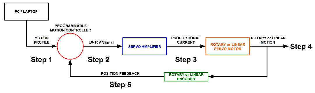
Step 1. A program or motion profile will be written on a PC or laptop and downloaded to the motion controller. This program will contain parameters such as speed, acceleration, deceleration, PIDs, desired position, etc…
Step 2. Based on the program parameters, the motion controller will send a +/- 10V reference signal to the servo amplifier.
Step 3. The servo amplifier will take the reference input signal and provide the necessary current to generate the required force from the motor to move to the desired position.
Step 4. The motor will move to the desired position at the programmed speed and acceleration.
Step 5: Motor position is sent back to the controller (typically 500 times per second) to verify that the desired position has been reached and maintained.