A DC linear servo amplifier is required to provide power to the torquer.
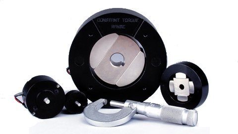
The torquers are typically supplied unhoused without bearings or a shaft, but can be supplied housed if required.
Coupling the torquer to your bearing system and a rotary encoder or other feedback device yields a system that is capable of intricate angular position, velocity, and acceleration control.
Low moving inertia of the rotor assembly allows for high angular acceleration of the payload.
The small length to diameter ratio allows the torquers to fit in spaces where conventional rotary brush and brushless DC motors will not.
It should be noted that, angular excursions of greater than 180º (up to 360º) can be achieved by modifying the winding of the stator assembly. In this case the coil assembly will have 4 leads and it will have to be commutated.
Advantages:
- No Torque Ripple
- High Angular Acceleration
- No Commutation
- Brushless
- Low Profile
Applications:
- Aerospace
- Semiconductor
- Medical
- Military
H2W Technologies offers 2 distinct types of limited angle torque motors.
1. TMR Series Limited Angle Torque Motor - is a toroidally wound iron core stator with a 2 ,4 or 6 pole permanent magnet rotor. This torque motor can provide angular excursions up to 180º. It is typically supplied without bearings, shaft or housing to allow for direct mounting to customer supplied bearing system.
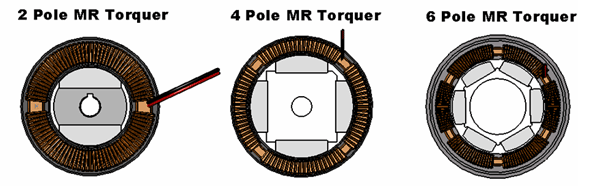
The TMR Series is comprised of a toroidally wound, stationary, coil assembly with a multi-pole permanent magnet rotor.
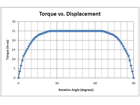
Rotor: The rare earth permanent magnet rotor always has an even number of poles, with any where from 2 to 6 poles. The maximum angular excursion with a 2-pole rotor is 180º, with a 4 pole rotor is 90º, and with a 6 pole rotor is 60º. The torque will drop off to zero at the extreme ends of the travel. For constant torque over the required rotation, the angular excursion will always be less than numbers mentioned above.
The rotor assembly is installed within the ID of the stator assembly. There is a magnetic attractive force between the stator and the rotor. When the stator is perfectly concentric within the rotor, the radial magnetic attractive forces are equal and opposite and they cancel each other out.
Stator: The stator is comprised of a “soft”magnetic steel toroid that is electrically insulated. Multiple sections of insulated copper magnet wire are toroidally wound on the stator toroid. Only 2 leads are brought out from the stator assembly.
The rotor assembly is installed within the ID of the stator assembly. There is a magnetic attractive force between the stator and the rotor. When the stator is perfectly concentric within the rotor, the radial magnetic attractive forces are equal and opposite and they cancel each other out.
2. TWR Series Limited Angle Torque Motor – is an arc segmented multipole permanent magnet stator with a low inertia copper magnet wire rotor. Angular excursions are typically less than 90º. This torquer is supplied with out a shaft or bearing.
The TWR Series is comprised of a stationary, arc segmented, multipole permanent magnet stator assembly with a low inertia wound wire rotor.
Rotor: The rotor is made up of a single coil of bondable copper magnet wire. The coil is wound and preformed into the desired shape. It is held together with the bonding agents in the wire. It can be encapsulated with aluminum or plastic brackets in order to provide a means for mounting the rotor to the bearing system and payload. The maximum angular excursion is less than 90º.
Stator: The stationary stator assembly consists of multipole permanent magnets that are bonded to steel plates. The 2 opposing steel plates are spaced apart to provide a gap using end plates. The coil rotor assembly moves angularly within this gap. There is no magnetic attractive force between the stator and the rotor.
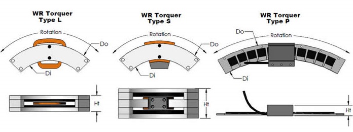
The TWR Series Torquers are available in 2 configurations.
The low profile (Type L) configuration has a smaller overall height which allows it to fit in a more compact space, but has less angular rotation for a given stator arc segment.
The second configuration (Type S) has a larger overall height but has typically twice the angular rotation per given stator arc segment when compared to the Type L torquer.
- No Torque Ripple
- High Angular Acceleration
- No Commutation
- Brushless
- Low Profile


Loading...
Required Electronics:
The motor requires a 1 phase brushless linear amplifier with power supply, that is rated with sufficient current and voltage to meet the motion requirements. A linear amplifier is required because of the very low inductance of the torquer coil assembly. A programmable motion controller is required to close the position loop on the system.
Environmental Considerations:
The torquer is a precision device with sensitive components, it should not be mounted in an environment that is wet or excessively dirty. The magnetic assembly is highly magnetic, it should not be placed in an area where loose steel particles can be drawn into the magnetic gap. The torquer should not be mounted in an environment with high ambient temperatures (>50ºC).
Mounting:
The torquer is typically supplied with out bearings and a shaft. This allows for the stationary and moving parts of the torquer to be mounted directly to the customers rotary payload assembly. The 2 components of the torquer should be mounted such that they are concentric to one another within .001". The rotor and the stator will have a mounting provisions to allow for attachment to the customers system.
Maintenance:
The torquer requires no maintenance.
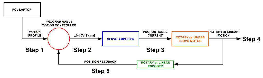
Step 1. A program or motion profile will be written on a PC or laptop and downloaded to the motion controller. This program will contain parameters such as speed, acceleration, deceleration, PIDs, desired position, etc…
Step 2. Based on the program parameters, the motion controller will send a +/- 10V reference signal to the servo amplifier.
Step 3. The servo amplifier will take the reference input signal and provide the necessary current to generate the required force from the motor to move to the desired position.
Step 4. The motor will move to the desired position at the programmed speed and acceleration.
Step 5: Motor position is sent back to the controller (typically 500 times per second) to verify that the desired position has been reached and maintained.