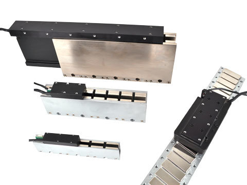
- Pick and Place Machines
- Coordinate measuring machines
- Laser and Water jet cutters
- Vision Inspection Equipment
- Unlimited stroke length
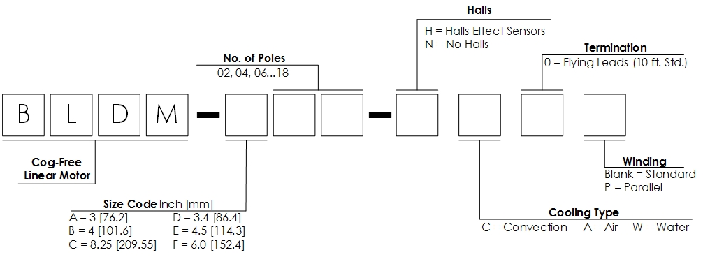
- Zero cogging
- High speed and accelerations of light loads
- Low moving mass
- Multiple motors coils inside a single magnet assembly
- Uses standard 3 phase brushless amplifier
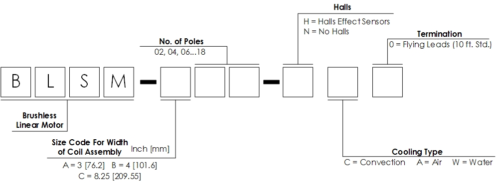
- Unlimited stroke length
- Magnetic-attractive force between coil assembly and magnet track used as preload for bearing system
- Coil features reduce cogging
- High speed and accelerations of heavy loads
- Multiple motors coils on a single magnet assembly
- Uses standard 3 phase brushless amplifier

Loading...


The motor requires either a trapezoidal or sinusoidal 3 phase brushless amplifier with power supply that is rated with sufficient current and voltage to meet the motion requirements. The inductance of the linear motor coil should be greater than the minimum load inductance of the servo amplifier.
Environmental Considerations:
The brushless motor is an open type motor and should not be mounted in an environment that is wet or excessively dirty. It should be protected with some type of bellows or cover when installed by the customer.
Mounting:
The brushless linear motor should be mounted to flat (better than .003"/ ft [246 microns / m] and stiff surface. Threaded and thru holes in the magnet assembly and threaded holes in the coil assembly are present for the mounting of the motor to the customers system. A cable carrier must be provided by the customer to route the motor and Hall Effect cable. The motor may be mounted in any orientation.
Maintenance:
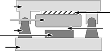
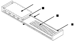
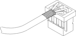
The ball bearing guides in the stage should be periodically lubricated with the manufacturers recommended grease. The open glass encoder scale should be wiped with a glass cleaner occasionally to ensure trouble free operation. Installation Refer to Figure 2-1. 1. Install the magnet assembly onto the machine mounting base. 2. With the slide assembly removed from the rails, install the coil assembly onto the slide, tightening the mounting screws. 3. Place a non–magnetic shim over the magnets, sized to cover all the magnets. (The shim thickness must be equivalent to the air gap specification. The normal air gap is 0.025” ± 0.005” unless otherwise specified). 4. Install and push the slide along the rails, positioning the coil assembly directly over the shim. (An alternate method is to install the slide on a set of rails that is identical to the one being used. Butt the temporary rails to the system rails and transfer the slide onto the system rails.) For either method, it is extremely important to uniformly tighten the mounting screws. Improper tightening will bend the primary or secondary and damage the motor. If there is not enough space to install the coil assembly as described, use this alternate procedure. Alternate Installation Refer to Figure 2-1. 1. Place the non–magnetic shim on the magnet track. 2. With a firm grip on the coil assembly, place one end of it on the shim and slide it into place, centered over the magnets. Be careful not to let the magnet and coil “Slam” together. 3. Align the fastening screw holes on the slide with the holes on the coil assembly. 4. Loosely install all the mounting screws. 5. Insert enough shims between the slide and the coil assembly to fill the gap. 6. Tighten all the mounting screws, alternating in a systematic manner while tightening such that the coil assembly is drawn–up evenly leaving a uniform air gap between the coil assembly and the magnets. This air gap must be maintained along the entire length of the magnet assembly i.e.; the coil assembly must never touch the magnets at any point when moving along the length of the magnet assembly and the air gap specification must be maintained at all times. 7. Remove the shim that sets the air gap prior to operation. Figure 2-1 Air Gap Adjustment
|
Motor Cable |
Hall Cable |
Limit Cable |
|||||
|
Signal Name |
Wire Color |
Signal Name |
Wire Color |
Signal Name |
Wire Color |
||
|
LinDrive |
Trap |
||||||
|
Motor Phase A (U) |
Red |
Black |
Hall 1 |
White |
Limit + Output |
White |
|
|
Motor Phase B (V) |
White |
Red |
Hall 2 |
Red |
Limit – Output |
Red |
|
|
Motor Phase C (W) |
Black |
White |
Hall 3 |
Black |
Home Output |
Black |
|
|
Motor Ground |
Green |
Hall Ground |
Green |
Limit & Home PWR * |
Brown |
||
|
Thermal Switch+ |
Blue |
Hall +5VDC |
Brown |
Limit & Home GND |
Green |
||
|
Thermal Switch– |
Orange |
Modular Magnet Track:
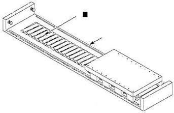
Installation Refer to Figure 2-3. Some magnets are provided in modular segments. This is the recommended procedure to install these modular magnet track sections.
Note: It is recommended that rubber coated tool handles be used to reduce injury (pinching fingers etc.) and protect the surface of the magnets.
1.Bolt the coil assembly onto the underside of the slide (carriage). Ensure the leads extend in the proper direction.
2.Install the magnet track on the base–plate adjacent to or between the linear bearing. Magnet track ends should not oppose each other. Place a 0.025” ± 0.005” thick non magnetic shim on the magnet track. The shim thickness must be equal to the recommended air gap (space between the coil assembly and the magnet track).
Figure 2-3 Modular Magnet Track Installation
3.Hold the slide with a firm grip and move it over the magnet track section/shim.
Note: The slide will be drawn forcefully towards the magnet track and may overshoot the rails if not held firmly. Check the space between the shim and the coil assembly. If the space between the shim and the coil assembly is large, uniformly loosen the mounting screws allowing the coil assembly to be fully and evenly lowered onto the shim.
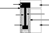
Insert another shim thick enough to fill the gap between the coil assembly and the slide, see Figure 2-4.
Tighten the mounting screws once again.
Figure 2-4 Air Gap Adjustment
5.Remove the air–gap setting shim from the magnet track before use.
Figure 2-5 Modular Magnet Track Installation
Operation Considerations:
The motor must always be operated within the specified operating parameter limits. Exceeding those limits will permanently damage the motor Refer to the motor specifications for operating parameter limits. The motor must never touch the magnets during operation.
The air gap must be maintained over full length of travel.
Remove the shim that sets the air gap between the motor and the magnets prior to operation.
Note: Be aware that the total bearing load includes the magnetic attractive force.
The following steps must be completed to ensure safe and proper operation.
1.Verify that all electrical wiring and cables are properly connected. Refer to the manual provided with the control for this information.
2.Adjust the servo drive current to match the motor’s current specification.
3.Refer to the motor specifications for operating parameters. Adjust the control parameters as necessary to the motor data specifications.
4.Adjust the control for the proper P.I.D. loop tuning. Begin at a low gain setting and increase the gain as necessary.
5.Strain relieve the wires prior to operating.
AY1763A00 Leadwire Connection:
|
Motor Cable |
Hall Cable |
Limit Cable |
|||||
|
Signal Name |
Wire Color |
Signal Name |
Wire Color |
Signal Name |
Wire Color |
||
|
LinDrive |
Trap |
||||||
|
Motor Phase A (U) |
Red |
Black |
Hall 1 |
White |
Limit + Output |
White |
|
|
Motor Phase B (V) |
White |
Red |
Hall 2 |
Red |
Limit – Output |
Red |
|
|
Motor Phase C (W) |
Black |
White |
Hall 3 |
Black |
Home Output |
Black |
|
|
Motor Ground |
Green |
Hall Ground |
Green |
Limit & Home PWR * |
Brown |
||
|
Thermal Switch+ |
Blue |
Hall +5VDC |
Brown |
Limit & Home GND |
Green |
||
|
Thermal Switch– |
Orange |
Brushless Linear Cog Free Servo Motor
1. Install the coil and magnet assemblies. While mounting the coil, be sure to adjust coil assembly so it is centered within the magnet assembly with equal air gap in the vertical and horizontal positions. See Figure 2-6.
2. Verify that the coil assembly is centered within the magnet assembly with equal air gap in the vertical and horizontal positions along its entire length of travel. The coil assembly must never be allowed to touch the magnets at any point from one end of travel to the other.
Note: For modular magnet mounting, magnets are mounted end–to–end without spacing. The mounting hole pattern is repeating and is unaffected by magnet segments. Hole pattern repeats across joining ends of magnets.
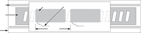
Multiple Coil Assembly Operation
In addition to maintaining an air gap, multiple coil assemblies must also maintain a spacing factor of 2.4”. In other words, the space between coil assemblies may vary, however, the distance from the front end of the first coil assembly to the front end of the next must be a multiple of 2.4”. See Figure 2-6.
Ensure that this factor is established at the time of installation
Figure 2-6 Air Gap Spacing
Operation Considerations
The motor must always be operated within the specified operating parameter limits. Exceeding those limits will permanently damage the motor.
The motor must never touch the magnets during operation. Equal horizontal and vertical air gap must be maintained. Remove the shim that sets the air gap between the motor and the magnets prior to operation. Note: Be aware that the total bearing load includes the magnetic attractive force. The following steps must be completed to ensure safe and proper operation.
1. Verify that all electrical wiring and cables are properly connected. Refer to the manual provided with the control for this information.
2. Adjust the servo drive current to match the motor’s current specification.
3. Refer to the motor specifications for operating parameters. Adjust the control parameters as necessary to the motor data specifications.
4. Adjust the control for the proper P.I.D. loop tuning. Begin at a low gain setting and increase the gain as necessary.
5. Strain relieve the wires prior to operating.
AY1763A00 Leadwire Connection
|
Motor Cable |
Hall Cable |
Limit Cable |
|||||
|
Signal Name |
Wire Color |
Signal Name |
Wire Color |
Signal Name |
Wire Color |
||
|
LinDrive |
Trap |
||||||
|
Motor Phase A (U) |
Red |
Black |
Hall 1 |
White |
Limit + Output |
White |
|
|
Motor Phase B (V) |
White |
Red |
Hall 2 |
Red |
Limit – Output |
Red |
|
|
Motor Phase C (W) |
Black |
White |
Hall 3 |
Black |
Home Output |
Black |
|
|
Motor Ground |
Green |
Hall Ground |
Green |
Limit & Home PWR * |
Brown |
||
|
Thermal Switch+ |
Blue |
Hall +5VDC |
Brown |
Limit & Home GND |
Green |
||
|
Thermal Switch– |
Orange |
LD9073A00 Hall Sensor Cable Connections (6 pin to flying leads)
| Pin# | Color | Description |
|---|---|---|
| 1 | Black | C |
| 2 | Red | B |
| 3 | N.C. | |
| 4 | Green | Ground |
| 5 | White | A |
| 6 | Brown | +5VDC |
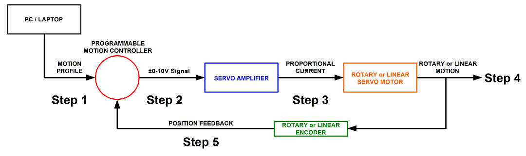
Step 1. A program or motion profile will be written on a PC or laptop and downloaded to the motion controller. This program will contain parameters such as speed, acceleration, deceleration, PIDs, desired position, etc…
Step 2. Based on the program parameters, the motion controller will send a +/- 10V reference signal to the servo amplifier.
Step 3. The servo amplifier will take the reference input signal and provide the necessary current to generate the required force from the motor to move to the desired position.
Step 4. The motor will move to the desired position at the programmed speed and acceleration.
Step 5: Motor position is sent back to the controller (typically 500 times per second) to verify that the desired position has been reached and maintained.