The motor is commutated using brushes on the moving permanent magnet secondary in conjunction with a stationary commutator bar on the coil assembly. This results in only the coils directly beneath the secondary with current flowing in them.
The short moving brush assembly is magnetically attracted to the long stationary laminated coil assembly. A customer supplied bearing system is required to guide the moving secondary and to maintain a .025” [0.63 mm] gap between the secondary and the coil assembly.
The power to the motor (from a customer supplied PWM DC servo amplifier) is supplied to the moving secondary via a power cable. The resultant force is proportional to the input current.
The low overall height (1.65” [41.9 mm]) of the brush motor allows it to fit into a very compact space The low moving mass of the secondary allows for higher accelerations of light payloads.
The motor comes in different widths and secondary lengths to meet different force and packaging requirements.
Advantages
- Low profile and small cross section
- Available in many different widths and lengths
- High Acceleration of light loads
- High Speed
- Uses low cost PWM amplifier
Applications
- Pick and Place Machines
- Coordinate measuring machines
- Parts transfer
- Inspection Machines
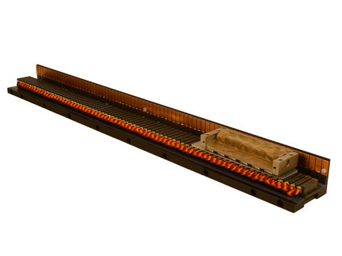
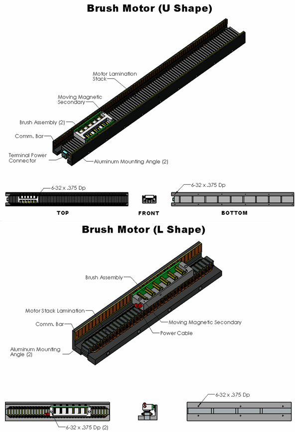
The Linear Brush Motor consists of 2 main parts:
- Long Stationary Coil Assembly: The laminated motor stacks are insulated and bonded together. The copper coils are inserted into insulated slots in the stack. The ends of the coils are brought out and soldered to the commutator bar. An aluminum mounting angle and a mounting bar are bolted to each side of the lamination stack. Threaded mounting holes in the angle or "T" nuts are available to mount the coil assembly to the customer supplied base plate. The coil assembly is available in widths from 2.0" to 5.0 " [50 mm to 125 mm]. The length of the coil assembly is a function of the stroke. Single piece motors are available as long as 144 inches [3.6 m]. Longer motors will be made in sections.
- Short Moving Secondary Assembly: The secondary is made of nickel plated steel with permanent magnets bonded to bottom. A PCB with brushholders and brushes soldered on, is mechanically attached to the side of the secondary. Mounting holes are provided for attaching the secondary to the moving member of the customer supplied table assembly. The secondary comes in different widths and lengths, depending on the required force. Multiple secondaries can be supplied with a single coil assembly to allow for independent moving heads or they can be coupled together to produce larger forces. The standard lengths for the secondaries are 4.38" for BRA motors and 9.56" for BRB motors.

Loading...
Required Electronics:
The motor requires a single phase brush type PWM amplifier with power supply, that is rated with sufficient current and voltage to meet the motion requirements. The inductance of the linear motor coil should be greater than the minimum load inductance of the servo amplifier.
Environmental Considerations:
The brush motor is an open type motor and should not be mounted in an environment that is wet or excessively dirty. It should be protected with some type of bellows or cover when installed by the customer.
Mounting:
The DC brush motor should be mounted to flat (better than .003"/ ft [246 microns / m] and stiff surface. Threaded holes on the bottom of the coil assembly or optional thru holes are present in the aluminum angles to allow for the mounting of the motor to the customers system. The moving secondary assembly has threaded holes on the top surface for attaching it to the customer supplied moving table. The motor may be mounted in any orientation. When mounting the stage with the secondary moving vertical, it should be noted that the stage will be required to generate additional force due to gravity and that the stage will slide down to the bottom when power fails.
Mounting:
The motor primary must be aligned (parallel) to the equipment guide ways within 0.005” (0.127mm) on each end. Use gauge blocks and shims as necessary. Precise parallel alignment of the motor to the equipment guideways is required. Align the stationary half of the motor to the guideways. Then align the moving half with the stationary half.
When securing the primary to the equipment base do not allow the screws to penetrate the motor more than .25” deep (to prevent damage to the motor windings).
To mount the motor secondary, slide the table over the secondary and align the mounting holes. The secondary is to be secured to the moving table with screws after the proper amount of shims are added to maintain an air gap of .015” min. to .020” max. (unless otherwise specified) between the secondary and the primary. This is achieved by ensuring that the plastic shim provided does not bind anywhere over the length of the primary when moving the table top with secondary back and forth by hand.
The plastic shim between the primary and the secondary can now be removed. Be sure that the secondary is centered and runs parallel to the commutator to within .005” at each end.
Electrical Check:
With an ohmmeter across input terminals, verify that the resistance reading does not drop to zero when the secondary / commutator assembly is moved over the entire length of the stationary primary. If a zero reading is observed, inspect the connections between the commutator brushes and the power input wires. In addition, inspect the connections between the motor windings and the commutator bar.
Motor Removal:
Insert the plastic shim between the primary and secondary to maintain the air gap. First, disconnect the power input wires. Next, remove the screws between the secondary and the moving table as this allows the secondary to sit on the primary. Then remove the mounting screws between the primary and the base. Finally, the complete motor assembly can be removed and placed on a level, flat surface.
Secondary Removal:
If just the secondary must be removed,slide the table with the secondary attached, to one end of the primary. Insert a .015” minimum plastic shim between the secondary and the primary to maintain the air gap. Remove the screws between the secondary and the sliding table. Move the table out of the way and slide the secondary out using extreme caution so as to not damage the brushes. If brushes are worn out, contact Baldor for replacement.
Secondary Reinstallation:
Place .015” minimum plastic shim on primary face. Next place .015” min fiberglass shims on the brush assembly and completely depress the brushes into their holders. With the brushes toward the commutator bars, slide the secondary onto the primary face (with the shim in place). When the secondary is in place, gently remove the shim from between the brushes and commutator bars.
Note: Ensure that the shim between commutator and brushes has rounded ends and that they do not cut the leads to the commutator bars.
Refer to “Mounting” instructions to reinstall.
Brush Motor Connections:
Black / Red (+)
White (–)
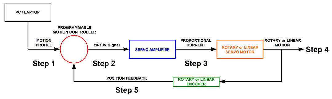
Step 1. A program or motion profile will be written on a PC or laptop and downloaded to the motion controller. This program will contain parameters such as speed, acceleration, deceleration, PIDs, desired position, etc…
Step 2. Based on the program parameters, the motion controller will send a +/- 10V reference signal to the servo amplifier.
Step 3. The servo amplifier will take the reference input signal and provide the necessary current to generate the required force from the motor to move to the desired position.
Step 4. The motor will move to the desired position at the programmed speed and acceleration.
Step 5: Motor position is sent back to the controller (typically 500 times per second) to verify that the desired position has been reached and maintained.