It is important to note that servo system integration can be somewhat involved and should be completed under the guidance of an experienced servo engineer. You may contact H2W Technologies and speak with one of our servo engineers so that they may assist you in selecting the correct components for your particular application.
The closed loop servo diagram below outlines what components are necessary in order to have a complete closed loop system. Depending on your unique application, you may require additional components.
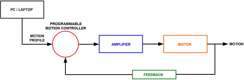
PC/Laptop
A Widows based computer is usually required. Most programmable motion controllers require software to be installed in order to program the controller. The motion profiles will be written using this software and then downloaded to the controller. Depending on the controller selected, a communication method such as Serial RS-232/RS-485, Ethernet, & USB will be needed.
Programmable Motion Controller Selection
A controller which can run the desired motion profile must be selected. The controllers are available in both stand alone and PC bus configurations. They are available as single or multiple axis (up to 32 axis). Factors such as motor & feedback type used will determine the type of controller selected. Most controllers have I/O circuits which allow the connection of components such travel limit and home switches. Some controllers have the capability of running secondary tasks such as executing more than one program at a time and data acquisition.
Amplifier Selection
An amplifier capable of providing the needed current and voltage to make the desired move must be selected. In order to size the amplifier with the linear motor, the continuous and peak current, back emf (to determine required DC bus voltage) and the motor resistance and inductance should be known. The amplifier current controls the output motor force and the DC bus voltage of the amplifier determines the maximum velocity of the positioning stage. Depending on the size (current ratting) of the amplifier selected it will require DC input via an external power supply or AC (single or three phase up to 230AC) power.
Depending on the type of linear motor being used, a specific type of amplifier must be selected.
3-Phase Brushless Linear Motor
Voice Coil Motor
Stepper Motor
Motor Selection
A motor that will give the desired force over the required travel distance must be selected.
Feedback Selection
A feedback device which will allow the system to achieve the desired accuracy & repeatability must be selected.
The closed loop servo diagram below outlines what components are necessary in order to have a complete closed loop system. Depending on your unique application, you may require additional components.
PC/Laptop
A Widows based computer is usually required. Most programmable motion controllers require software to be installed in order to program the controller. The motion profiles will be written using this software and then downloaded to the controller. Depending on the controller selected, a communication method such as Serial RS-232/RS-485, Ethernet, & USB will be needed.
Programmable Motion Controller Selection
A controller which can run the desired motion profile must be selected. The controllers are available in both stand alone and PC bus configurations. They are available as single or multiple axis (up to 32 axis). Factors such as motor & feedback type used will determine the type of controller selected. Most controllers have I/O circuits which allow the connection of components such travel limit and home switches. Some controllers have the capability of running secondary tasks such as executing more than one program at a time and data acquisition.
Amplifier Selection
An amplifier capable of providing the needed current and voltage to make the desired move must be selected. In order to size the amplifier with the linear motor, the continuous and peak current, back emf (to determine required DC bus voltage) and the motor resistance and inductance should be known. The amplifier current controls the output motor force and the DC bus voltage of the amplifier determines the maximum velocity of the positioning stage. Depending on the size (current ratting) of the amplifier selected it will require DC input via an external power supply or AC (single or three phase up to 230AC) power.
Depending on the type of linear motor being used, a specific type of amplifier must be selected.
3-Phase Brushless Linear Motor
- Analog Brushless Amplifier
- These amplifier are trapezoidally commutated using the hall effects. For point to point positioning this is an ideal solution because of their lower cost.
- Digital Brushless Amplifier
- These amplifiers are sinusodially commuted. They may use the encoder and hall effects to achieve this or the encoder only. Sinusodial commutation allows for smoother motion with lower velocity ripple. These amplifiers generally require software in order to do the initial motor setup and commutation settings. These setting are stored to the amplifiers internal memory. Some amplifiers have different levels of intelligence to run additional tasks such I/O capabilities and basic motion profiles.
Voice Coil Motor
- Brushed Type Amplifier
- This type of amplifier is used to run single phase (2 lead) motors. These amplifiers can have some type built in intelligence and may require additional software.
- Linear Amplifier
- This type of amplifier is ideal for running low inductance motors.
Stepper Motor
- Stepper Driver / Microstepping Driver
- This type of driver requires a pulse and direction (generated by controller/indexer) input signal in order to move the motor. Microstepping drivers have the ability to move in smaller step pulse incriments in order to achieve smoother motion and better accuracy/repeatability.
Motor Selection
A motor that will give the desired force over the required travel distance must be selected.
- 3-Phase Brushless Linear Motor
- The 3 phase brushless (or AC servo) linear motors are ideal for long stroke high velocity/acceleration applications. Large motors with high forces are available. They are capable of very precise position, velocity and acceleration control when coupled with a linear encoder.
- Voice Coil Motor
- Voice coils are ideal for short stroke (typically less than 2 inches) applications. Their compact size allows them to fit into small spaces. They have very low electrical and mechanical time constants. The low moving mass allows for high accelerations of light payloads.
- Linear Stepper Motor
- Linear stepper motors are ideal for open loop positioning applications with light payloads. Linear stepper motors are capable of very precise position, velocity and acceleration control when coupled with a microstepping drive and indexer. Feedback Selection A feedback device which will allow the system to achieve the desired accuracy & repeatability must be selected.
Feedback Selection
A feedback device which will allow the system to achieve the desired accuracy & repeatability must be selected.
An open loop system is a system where you define the output by an input signal, however there is no external feedback (i.e. force transducer, encoder, LVDT, etc.) that verifies the output or affects the input. Common examples of open loop systems are running a voice coil actuator (often with springs) with a function generator and an amplifier or a linear stepper motor using a micro-stepping driver. These are systems that are externally adjusted and tuned, instead of a control system tuning through software.
Advantages:
Simple control design, low-cost and easy to build, stable performance
Disadvantages:
Difficult or inability to make small modifications after setup, unable to determine accuracy or reliability of commanded vs. actual
Examples
Voice Coil Motor using a Function Generator
Linear Stepper Motor
Multi Axis: Linear Stepper Motor